BAFFLE SYSTEMS
STAMFORD BAFFLE 3.0
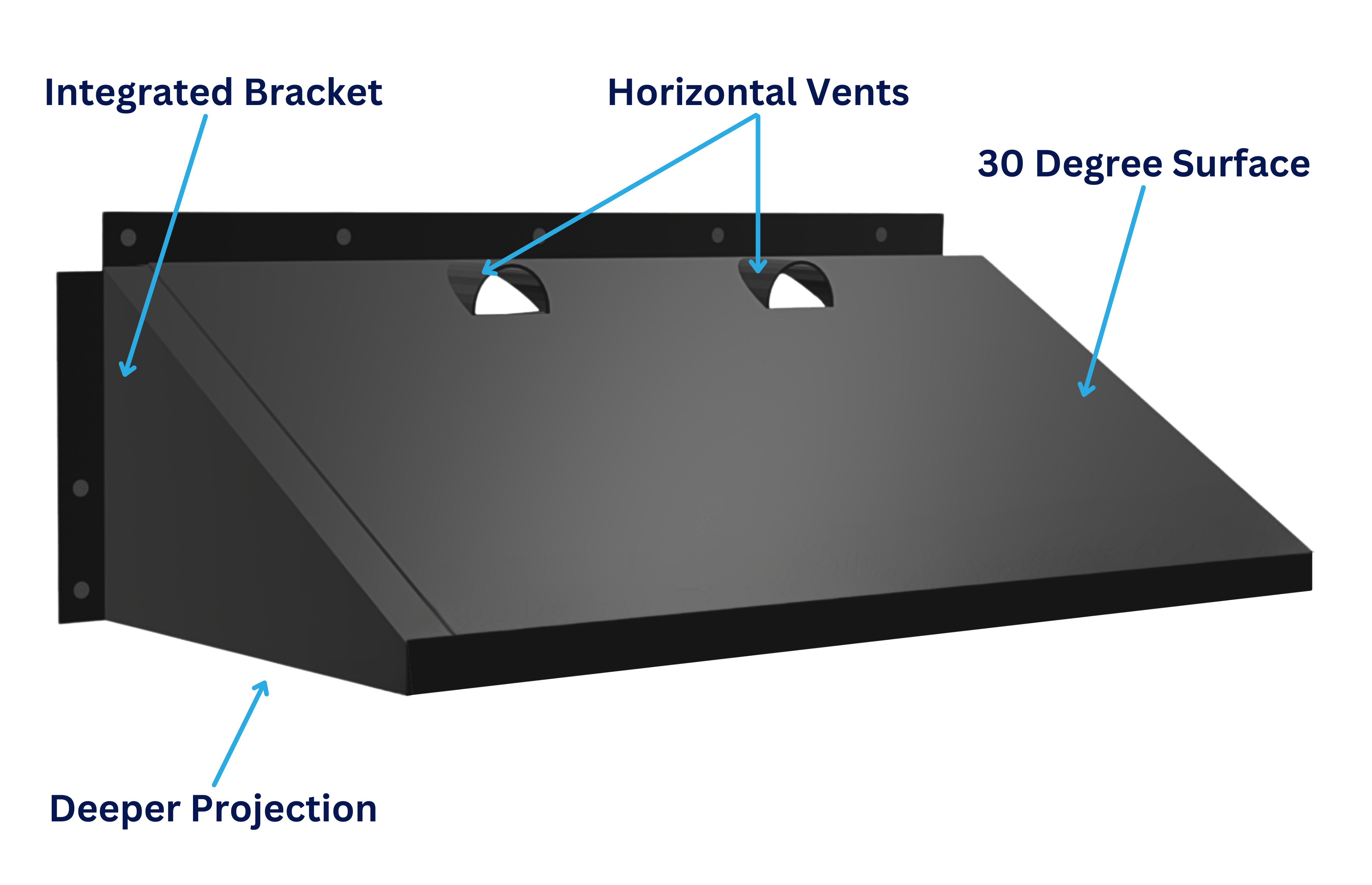
The New Stamford Baffle 3.0 is everything the Stamford Baffle 2.0 is with added efficiency. The new horizontal vents create a jet-like flow that is directed away from the launder/weir wall and won’t impede on the surface currents. You’ll see a reduction in turbidity at the weir and an increase in baffle performance. The Stamford Baffle 3.0 features the 30-degree inclination angle as measured down from the horizontal and greater horizontal projection from the clarifier wall, calculated as a function of the clarifier diameter.
WALL MOUNTED BAFFLE
In clarifiers with outboard launders, the baffle mounts to the clarifier wall with the bottom of the baffle positioned mid-way between the top of the sludge blanket and the bottom of the weir. In clarifiers with inboard launders, the baffle will perform most effectively mounted to the tank wall below the launder, so long as there is sufficient vertical clearance to mount the baffle with the bottom of the baffle two feet or more above the top of the blanket.
LAUNDER MOUNTED BAFFLE
If there is insufficient vertical clearance, the baffle should be mounted to the lower inboard corner of the launder trough. The width of the launder should be included in calculating the horizontal projection of the baffle, but the projection should never be less than 24”.
THE ORIGINAL NEFCO STAMFORD BAFFLE
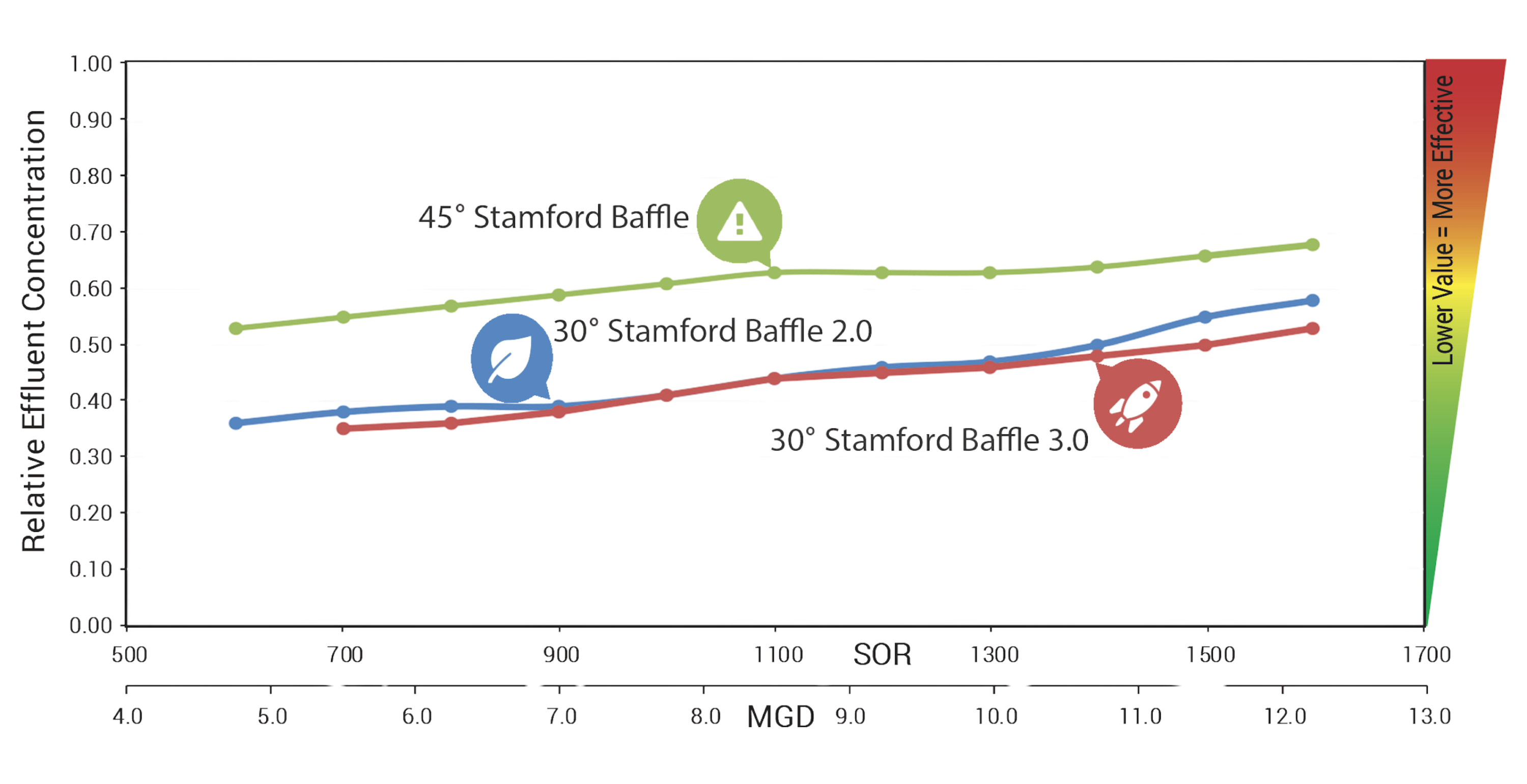
The original NEFCO Stamford Baffle was inclined at 45° and had a relatively small horizontal projection factor. That baffle reduced the clarifier’s total suspended solids (TSS) by roughly 40%. The design quickly became the industry standard. NEFCO’s baffle included two proprietary features: an integrally molded support bracket that simplified installation, and gas vents molded into the mounting flange at the top of the baffle.
Through our continued research and development of the Stamford Baffle design, NEFCO offers the Stamford Baffle 3.0. The most efficient Stamford Baffle on the market!
The new Stamford Baffle 3.0 offers the unprecedented performance of the Stamford Baffle 2.0 design combined with the added efficiency of horizontal vents to provide even better TSS reduction (up to 70%) and lower turbidity at the weir for improved clarifier performance.
The Stamford Baffle 3.0 features the 30-degree inclination angle as measured down from the horizontal and greater horizontal projection from the clarifier wall, calculated as a function of the clarifier diameter.
DENSITY CURRENTS
NEFCO’s Stamford Baffle 2.0 and the new for 2019 Stamford Baffle 3.0, retains all the unique features of the original NEFCO Baffle. The baffle is comprised of individual baffle sections or “modules.” Each module combines the baffle panel, the bracket, the vents and the mounting and stiffening flanges in a one-piece molded fiberglass unit that offers a few advantages:
- The solid integral bracket at the end of each baffle panel reduces the current velocity below the baffle and contributes to settling.
- With the integrally molded bracket and other reinforcements, this baffle requires only one bracket per panel.
- The one-piece, modular design cuts installation time in half.
The Stamford Baffle 3.0 system is readily converted to NEFCO’s new Dual Surface Baffle. This dual surface configuration is designed for larger clarifier operating at very high flows, including combined sewer configurations.
3.0 VS. 2.0
The New Stamford Baffle 3.0 is everything the Stamford Baffle 2.0 is with added efficiency. The new horizontal vents create a jet-like flow that is directed away from the launder/weir wall and won’t impede on the surface currents. You’ll see a reduction in turbidity at the weir and an increase in baffle performance.
DUAL SURFACE BAFFLE SYSTEMS

The Dual Surface Baffle has a wedge-shaped configuration with identical upper and lower surfaces. The upper surface is identical to the Stamford Baffle 3.0® design, using the 30° inclination angle and the same algorithm to determine the baffle’s horizontal projection based on clarifier diameter. The lower surface is a mirror image of the upper and is inclined back to the clarifier wall. The configuration of the baffle allows the lower portion to be retrofitted to any existing NEFCO Stamford Baffle, upgrading it to the Dual Surface configuration.
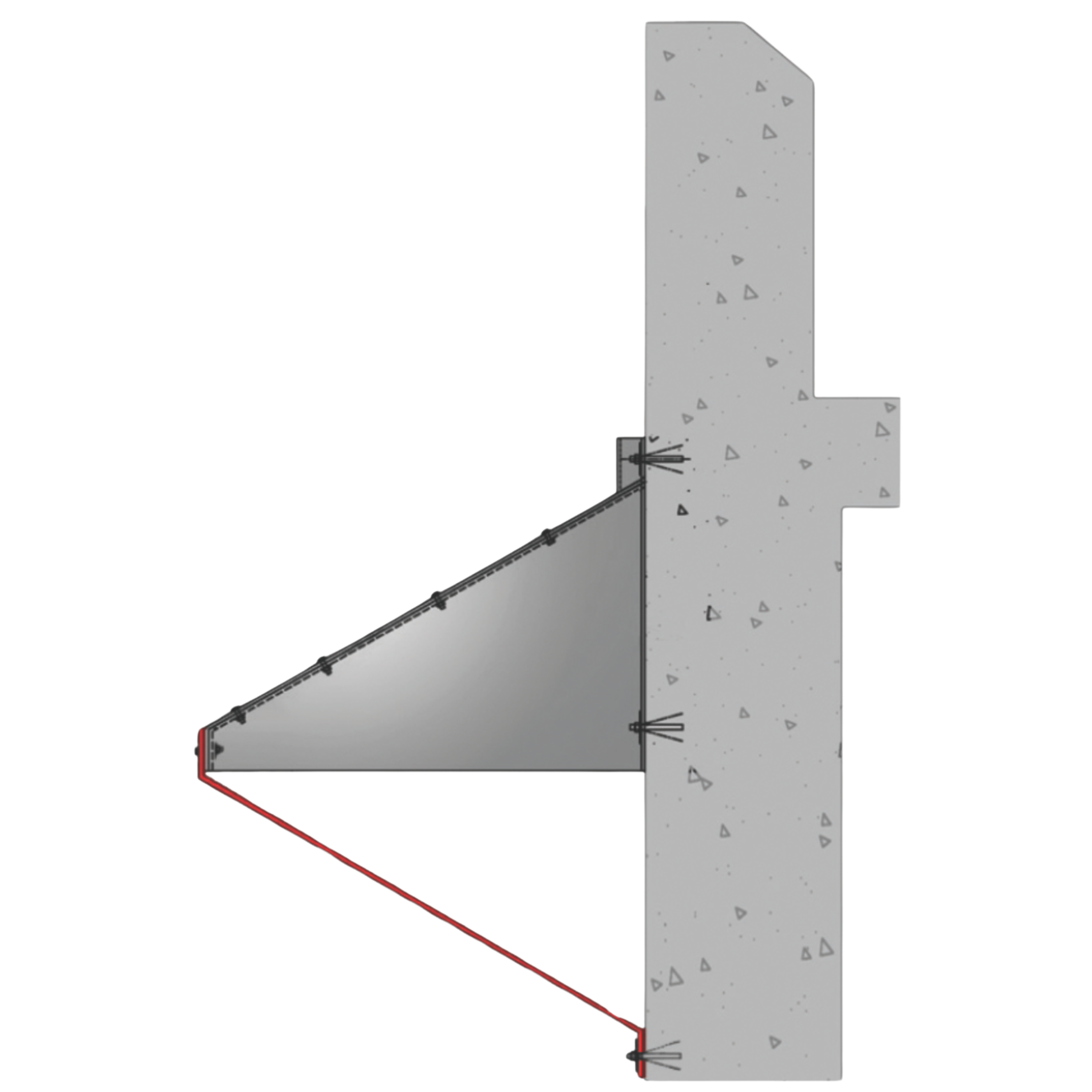
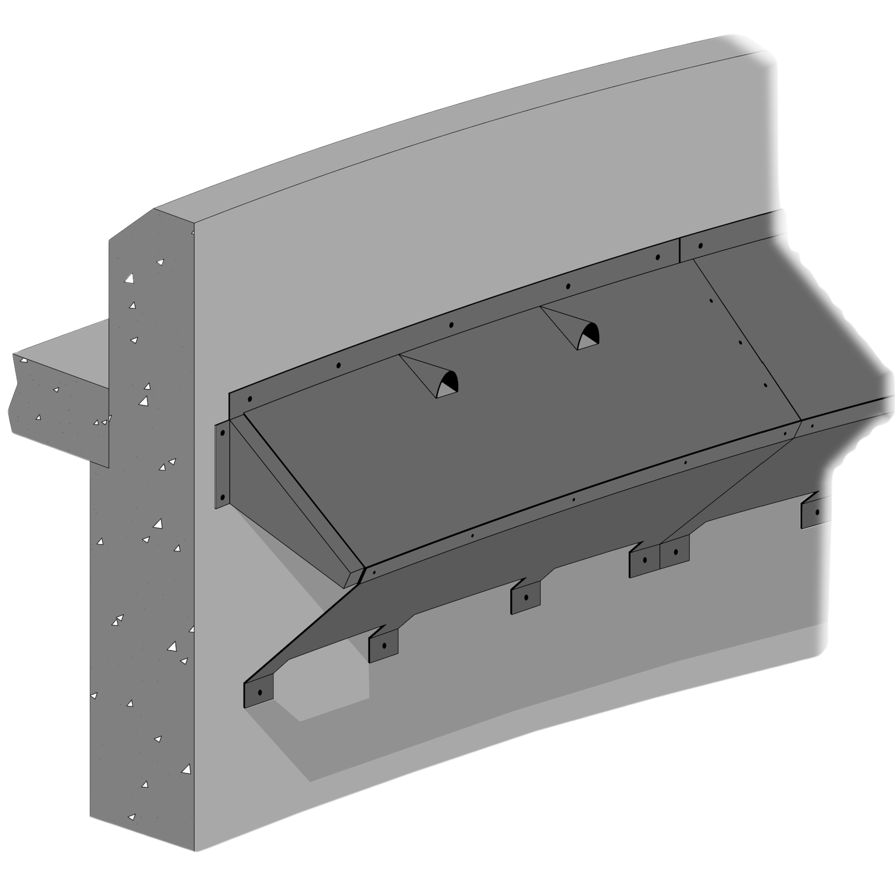
THE DUAL SURFACE BAFFLE
The Dual Surface Baffle has a wedge-shaped configuration with identical upper and lower surfaces. The upper surface is identical to the Stamford Baffle 2.0® design, using the 30° inclination angle and the same algorithm to determine the baffle’s horizontal projection based on clarifier diameter. The lower surface is a mirror image of the upper and is inclined back to the clarifier wall. The configuration of the baffle allows the lower portion to be retrofitted to any existing NEFCO Stamford Baffle, upgrading it to the Dual Surface configuration.
An advanced Density Current Baffle specifically designed for high flow situations.
The Dual Surface Baffle continues to reduce TSS as flow increases.
The Wedge Shape is retrofitted or newly designed with the latest technology to achieve performance at a higher level.
The Dual Surface Baffle modules are attached to the tank wall with stainless steel anchors. This baffle is not intended for use in clarifiers with inboard launders. Mounting holes are factory drilled and sealed. Adjacent modules fasten together at a molded recess that forms a ship-lapped joint. Sections of the baffle may be cut as required to fit around piping and other obstructions. The baffle’s laminate features a tough, corrosion-resistant and uv-suppressed fiberglass resin specifically formulated for use in industrial and municipal waste treatment applications.
NEFCO’S CFD BAFFLE STUDY
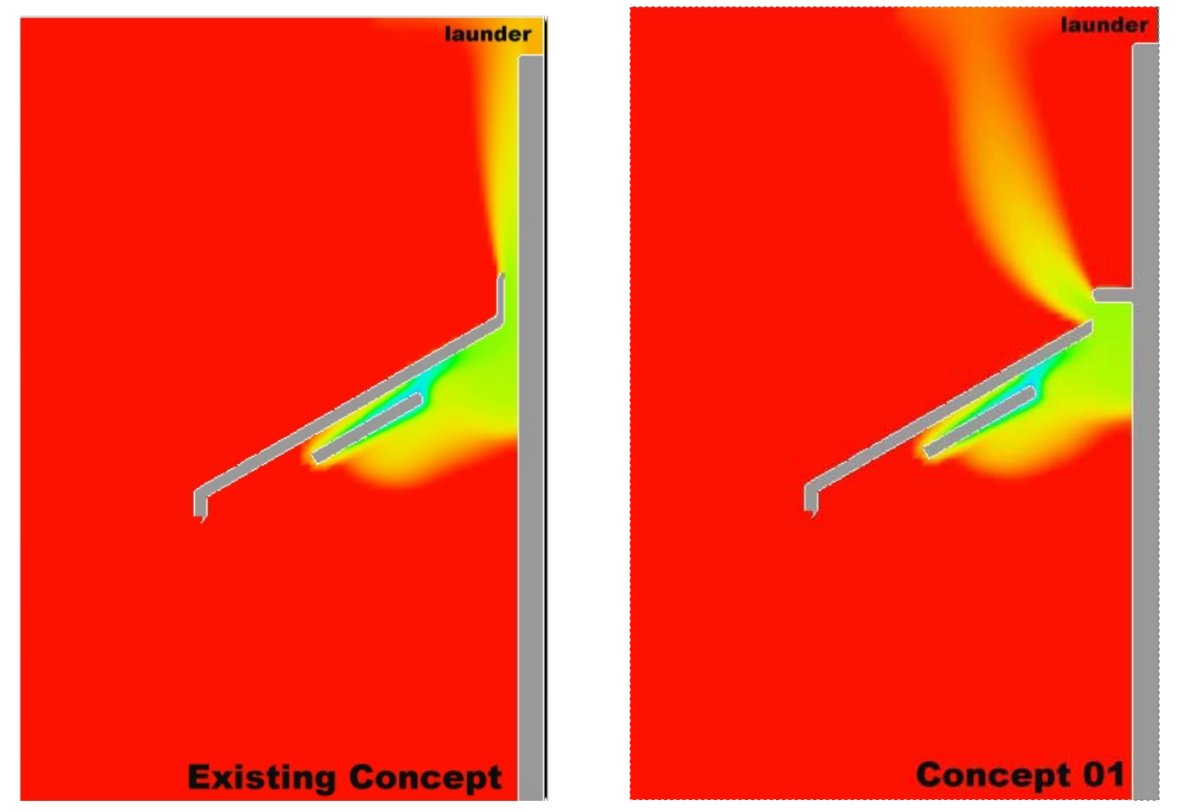
NEFCO’s Dual Surface Density Current Baffle was developed through the company’s CFD Baffle Study. This baffle is designed for larger clarifiers operating at very high flow and has the potential to reduce effluent solids by as much as 80%. As a part of its CFD Baffle Design Study, NEFCO engineers began to explore alternative baffle configurations that might further improve baffle performance. These new configurations were inspired by the predicted flow patterns of the density currents around the baffle.
THE DESIGN
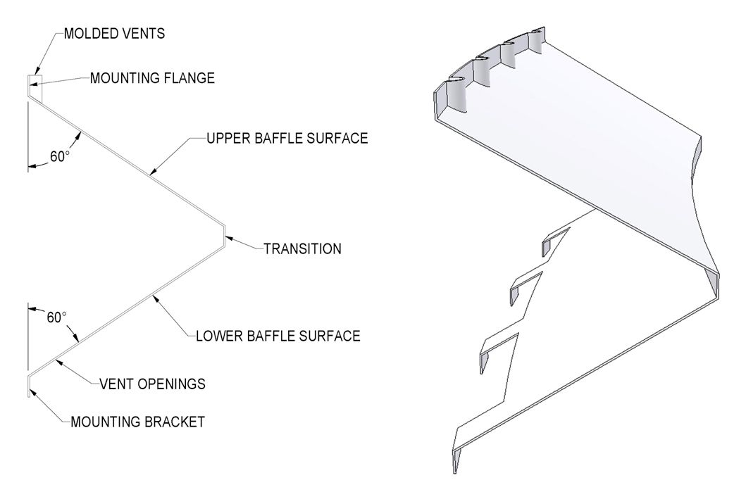
The basic design of the Dual Surface Baffle is shown in this diagram. The baffle is wedge-shaped, with identical upper and lower surfaces that fasten to the tank wall. The inclination angle and horizontal projection of the Dual Surface Baffle are identical to those of the Stamford Baffle 3.0®. The upper surface of the baffle includes the integrally molded vents of Stamford Baffle 3.0®.
The Dual Surface Baffle consists of individual upper and lower baffle sections or “modules.” Each module combines the baffle panel, the baffle bracket (upper panel only), the vents, mounting, and stiffening flanges in a one-piece molded fiberglass unit eight feet long. The vents in the upper section are the standard, integrally molded vents found in Stamford Baffle 3.0®. The lower section features large rectangular openings that are formed as a part of the baffle mounting flanges. These openings serve to inhibit solids from collecting inside the baffle and provide a convenient means of cleaning the baffle periodically, if necessary.
VIDEO & DOWNLOADS
OUR PROCESS
At NEFCO, we have a proven track record of delivering results. All custom products are made to order and our team is committed to providing excellent customer service. We are always on a mission to improve and innovate on all of our patented products.

FREQUENTLY ASKED QUESTIONS
Why is fiberglass a better choice than steel for wastewater and water reclamation facilities?
How does fiberglass improve the longevity of infrastructure in wastewater facilities?
Does fiberglass require less maintenance than steel in water treatment applications?
How does fiberglass perform in extreme conditions found in wastewater facilities?
Is fiberglass more cost-effective than steel for wastewater treatment infrastructure?
How does fiberglass enhance safety in wastewater facilities?
Can fiberglass structures withstand chemical exposure in water reclamation plants?
How does fiberglass compare to steel in terms of installation and handling?
What are the environmental benefits of using fiberglass in wastewater treatment facilities?
Where is fiberglass commonly used in wastewater and water reclamation facilities?
download brochure
Please click on button below to download product brochure.

Let’s Work Together
8895 N. Military Trail, Building C Suite 100
Palm Beach Gardens, FL 33410
sales@nefco.us
Monday – Friday 8AM – 5PM

